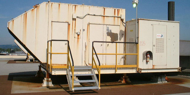
Domtar's "Temprite" Make-up Air units are located on the roof of the Coater Building. Above we see Unit Number 105. All the units, except for Temprite # 447 supply air to the Coater Building. Temprite #447 supplies air to the dry end of #2 Paper Machine. As you read over these notes, be sure to click on the Highlighted Links.
One of the more frequent duties of the engineer is to check and advance the make-up air inlet filters. The condition of the filters can be determined by observation of the filter medium itself or by the differential pressure across the filter as indicated by the Magnehelic gage. "The Magnehelic" registers the pressure drop in inches of water column. Thus, the higher the reading, the more clogged the filters. Usually a reading of higher than .50 inches indicates plugged filters and the necessity of advancing them. Usually advancing the filters to expose a few feet of new media is sufficient. To advance the filters, the engineer can either shut down the main blower fan or equalize the pressure across the filters by opening the doors. This allows the filter roll to advance without straining the chain and sprockets.
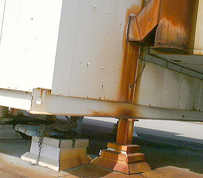
The main gas shut off for the individual Temprite Units are located under the units themselves. There is a chain available to lock these valves shut when performing maintenance on the burner or gas train.
Also note the location of the "test hole" in the furnace flue for testing the flue gas using our analyzer. This should be done at least once a year, along with testing of all the safety limit switches, over fire draft and furnace inspection.
- The list of items to check and the method of testing can be FOUND HERE.
- The testing results of all the Temprites over the years can be FOUND HERE.
The purpose of our five roof-top Temprite Units is to supply make-up air to the Coater and #2 Paper Machine buildings. This "make-up" air is important in that we use the air within the Coater building to support combustion. (Infra Red Dryers, SCAF Dryers). This make-up air also replaces air that is exhausted from hoods and exhaust fans.The make-up air is also important for air movement, elimination of condensation and cleaning the atmosphere of contaminants.
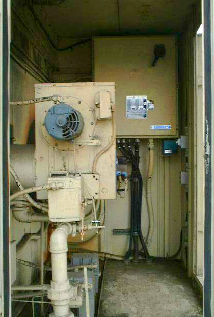
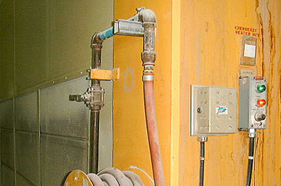
In the image to the left we see the typical arrangement of the Temprite gas train and oven-pack burner. CLICK HERE to see labeling of the different parts.
You will note the locations of the positioner linkage on the gas valve servo motor. When it is at the bottom mark, an "end switch" is opened and the burner will not start (No "call for heat" or "faulty thermostat")
Also note the resets for the high and low gas pressure cut-outs.
SSOV stands for "Safety Shut Off Valve" and refers to the Honeywell "Fluid Power" (hydraulic) slow opening/fast closing (one sec) Gas Safety valves. Check under these valves for leakage of hydraulic fluid.

The make-up air is indirectly heated in the Temprite Rooftop Units. The heating of this air is mainly for comfort reasons. (so that cold air is not chilling the building or personnel).
It is indirect heating in that the heat from the furnace passes to the make-up air through the furnace wall. At no time do the products of combustion ever enter the building. For this reason, there is "always" a negative "over fire draft" in the furnace, supplied by the ID Exhaust Fan. This negative pressure is measured at the "Furnace Inspection Door" with a Manometer.
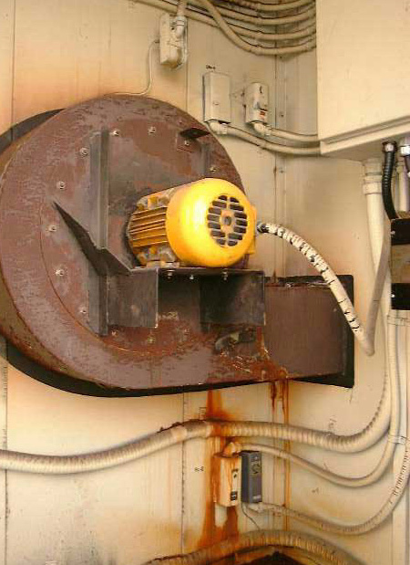
The image to your left is the same as above but from a different angle.... entering the "Control Cabinet".
CLICK HERE to see descriptions of more of the working parts. Now we see the Combustion Air Fan Motor and the "Combustion Air Switch" which is a sensitive pressure controller and must prove combustion air flow before allowing the burner to light.
Also note the location of the "Primary Controller" and it's reset button. Upon a call for heat, if all other limits are satisfied, this controller will put the burner through its 90 second purge. It will then light the pilot and start the 4 second "pilot establishing period". After this the gas SSOV's will open and establish the main burner flame. It will then monitor the flame via the detection rod.
The Temprites use an "Intermittent Pilot" whereby the pilot is ignited by the ignition spark and stays lit as long as the burner is in operation.
If there is a flame or a flame simulating failure the controller will lockout and will have to be manually reset. For example, if the detection rod is faulty, the primary controller will lockout.
Finally note the location of the main disconnect at the top of the electrical cabinet. This isolation switch should be locked open whenever any work is being performed on the Temprite. This is also the means of shutting down the main blowers locally.
The Exhaust Blower maintains a negative pressure in the furnace at all times. In the far corner of the control cabinet, above and below the blower are controllers and limit switches connected to the ductwork. CLICK HERE to have these labeled and explained.
Located at the top of the Blower is the air flow switch which must prove the flow of air through the furnace before the burner will light.
Next to the exhaust air proving limit switch is the FAN CONTROLLER. The Manual/Auto button should always be in the "Manual" position (Pushed in) allowing the make-up air blowers to stay on continually, regardless of what the air temperature is. This is necessary in order to continuously supply make-up air at all times.
Next to the main blower controller is the High Temperature Switch with "reset". When trouble-shooting, always check this reset along with the high and low gas pressure resets.
IN the bottom corner of the control cabinet are the DUCTSTAT AND FREEZESTAT. The freezestat
In an effort to standardize the individual settings and to conserve energy, we have set all the "room thermostats" to 19 degrees C. (66 degrees F). The "Duct Thermostats", in the cabinets of the Temprites, are always set 5 degrees below the Roomstats. The Ductstats are therefore set at 61 F. The combined signal from both these thermostats serve to position the gas valve to the burner.
If an engineer has a request to increase or decrease the temperature of the outlet of an individual Temprite, the engineer should increase or decrease the thermostat setting, which will allow the burner to cycle on or off as required to satisfy the call for heat. CLICK HERE to see location of the thermostat. When the unit is switched to "Summer" mode, the burner cannot come on with a call for heat (at night for example) and even when switched back to "Winter" mode, the "trial for ignition" will often fail due to condensation on the detector rod. Rather than the engineer on night shift having to go to the roof to reset a Temprite because the air blowing from the registers is cold and the unit will not start up, an adjustment on the thermostat setting will allow the unit to automatically fire up if the temperature falls. (on a call for heat). Of course, when summer finally does arrive, a the Air make-up units are switched to "summer mode".
Much more information and detail on each component and instrument involved with the Temprite Units can be found in the "manual" located in the Control Room cupboard or in the Chief's Office.